Medical Waste Incinerator Purpose
For a complete destruction of waste from various hospital services by heat treatment of high temperature in accordance with EU standard on emission requirement.
-Waste from health care activities
-Infections waste, laboratory cultures, waste form operation room isolations material in contact with infected patients, waste potentially being infected by pathogenic agents.
-Pathological waste, human fragments, blood, fetus, all body fluids, human tissues.
-Sculpts, needles, infusion sets, blades, glass
-Pharmaceutical waste.
-Chemical waste laboratory reagents, disinfectants
-Expired drugs.
-Low radiation radioactive element.
Medical waste incinerator: – Ecological Requirement
– No odor
-No fume
-Definitive treatment of waste
Medical waste incinerator: – Manufacturing Standards
-UL,CE, ASME, ISA EURO emission standard
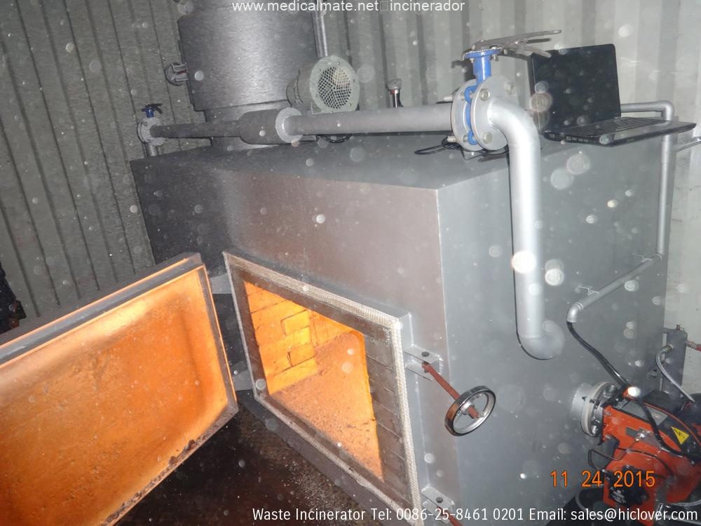
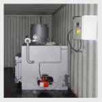
1.Medical waste incinerator
Construction – CS plate shells, FB reinforcement, cast refractory linings,
Insulation and 14 gage aluminum jacket.
Type of fuel – Oil fired (Diesel)
Burning Capacity – 250kg/hr and moisture up to 80%.
Duration -8-16/Continuous
Average fuel consumption – Very little as much as possible
Control Type – PLC based operation
Operating Temperature – Primary chamber 800oc ± 50
– Secondary Chamber 1050oc ± 50
Size of incinerator – Not more than 15mx7.20m
Chimney – Ø630x25meter height and 7mm thick CS.
Combustion efficiency- 99%
Mode of waste handling- Semi-automatic via ram loader.
Mode of ash handling – Semi-automatic via grate and ash trolley.
Pollution control equipment- Dry settlement zone
Doors- 1-waste charging door in primary chamber
1-clinker door in primary chamber
1-ash trolley access door in primary chamber
1-clean out door in secondary chamber
Burner – 2- ignition burner in primary chamber
2- after burner in secondary chamber.
Type- package mono block-fully automatic
Type of burner operation- modulation control
Forced draught fan- 1-primary air fan
1-secondary air fan
Fuel storage tank – Capacity- 2500liter above ground
– Material-6mm thick mild steel
– 2-diesel pump, gate valve, safety valve, strainer
Pipe, pressure gage, check valve, control board
Level indicator. Etc
Refractory/insulation thickness- not less than 225mm
Ram loader capacity- 0.75m3
Electrical supply- 380v/3ph/50 Hz
Finish and painting type- powder coated
Audio/ visual alarm system- burner lockout, overload fault
Electrical accessories- primary and secondary chamber temperature
Controller/indicator, auto controls, electrical
Control switches, push buttons, relays, contactors
Thermocouples, burner sequence controllers,
Timers, emergency stop and alarms.