Archive: July 21, 2023

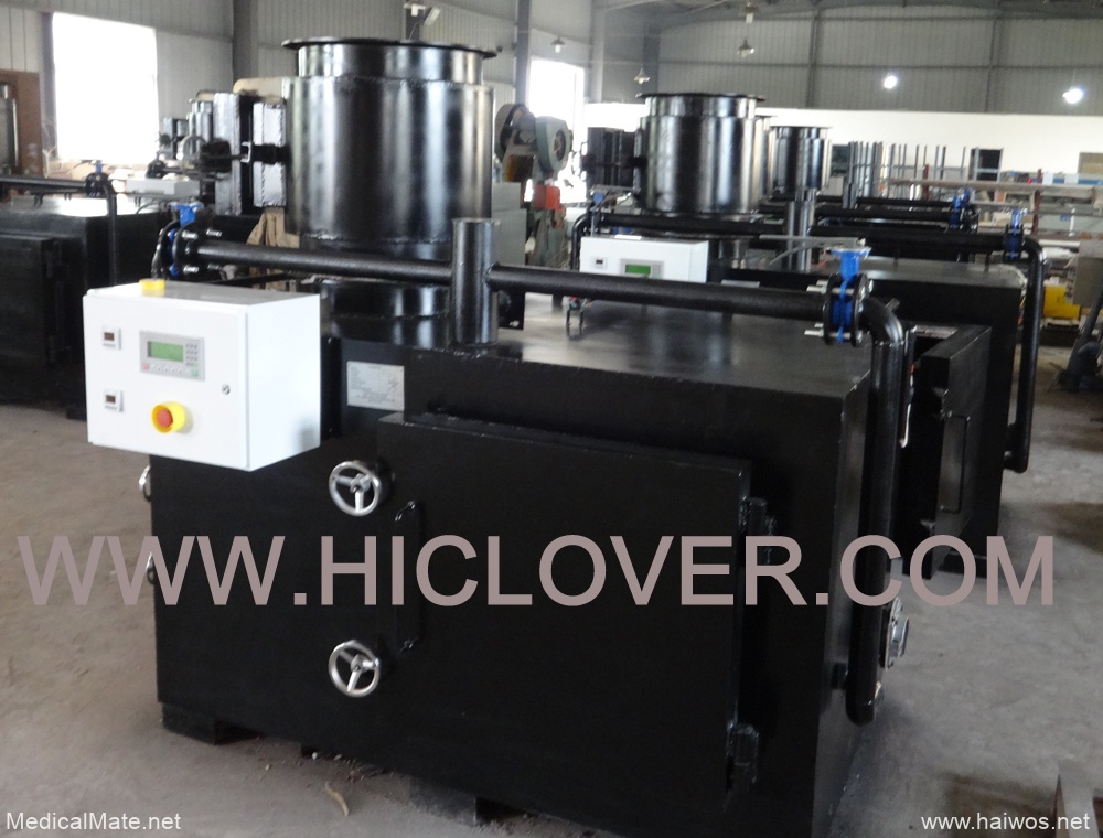
incinerator plant specification


1) Power Supply:
( a) Keys Supply:
( i) Singular Phase supply; 220– – 240V, 50Hz( ii) 3 Stage supply; 380– – 415V, 50Hz( iii) The power supply electrical outlet (sockets) for solitary stage supply system in the hospital is three pins as well as additionally adheres to BS1363.

(b) Change:( i) Keys modification is an usual concern, the performance requires to be affected by this problem a resistance of ± 15% or more in both the nominal voltage should certainly be permitted.
( ii) Keys Cut-off (black out) is a regular problem. Where required, Uninterrupted Power Supply (UPS) System should be consisted of to stay clear of damages of equipment as a result of sudden disruption in power supply.
( iii) There are spikes not necessarily from the secrets supply nonetheless results when specific plants or devices began.
( iv) Vendors must as a result validate to make certain that their power supply systems will not be affected by the above conditions.

2) Supply Of Water a) High quality: the mains supply is tough water. The supplier requires to check/modify their equipment with filters or descalers where required.
b) Anxiety: this varies and connected with frequent removed. Where needed, the company ought to consist of boosters or pumps to overcome this problem.
c) Where called for, representatives must contain water distillers

2-83 Location VI. Needs

3) Temperature degree: ambient temperature level varieties in between 21– – 450 C or even a lot more in inadequately aerated areas. The hottest month of the year is March. Environmental temperature level can be such that inferior rubber as well as also plastic items can easily melt or warped. Prospective buyers must make certain all items will certainly have the capability to endure such temperatures

4) Humidity: moisture is generally high concerning 65– – 90%. Electronic gadgets should be secured to prevent the impact of condensation.

5) Dirt: this is a significant concern specifically throughout the dry duration. Dust get in tools as well as congests filters. Additional safety and security needs to be provided where crucial along with where suitable extra filters offered to last not much less than 5 years continuous usage.

6) Vermin: these are additionally supplied as well as sometimes take part in equipment to chew cable tv along with pee on boards to create short circuit. This can be stopped by using vermin guard where required to prevent entry of such destructive pets.
7) The proposed tools has to adapt today ideal international standard such as ISO; CE; IEC, ANSI and/or BS

8) Language: a) All tags along with markings on the tools require to be in English language. b) All software program application programs in the suggested gadgets should remain in English language c) All handbooks need to remain in English language.

9) Each of the devices supplied requirement to be provided with client and additionally technological manuals. Guidelines on their use, storage space as well as also remedy must be clearly indicated in the handbooks and additionally where essential, on the tools.

10) Where ideal the following will use: a) Electrical Safety i) The tool needs to be supplied a line (power) cable of acceptable sturdiness, size, ampacity, and also top quality as well as additionally needs to be safeguarded with ideal stress and anxiety alleviations.
ii) The device ought to include, or the bidder or distributor have to provide, power plugs that are sufficient for the optimum voltage and also current of the device.
iii) The structure requires to be based as well as grounding resistance needs to not surpass 0.15 ohm.
iv) If the system is twin shielded, it ought to be so classified.
v) Electrical leak current from the structure of the gadget should not surpass 500µA per IEC 601-1 b) Effects of Fluids

Location VI. Needs 2-84

i) Individual as well as likewise operator safety and also safety and security as well as system efficiency require to not be detrimentally affected by liquid spills.
ii) If the system is influenced, it needs to fail safely.

c) Overcurrent Safety i) Loss of power to different other devices on the precise very same branch circuit as a result of internal equipment blunders need to be protected against by utilizing incorporates or breaker that are clearly labeled as well as easy to replace or reset.
Long-lasting markings near each fuse holder need to suggest fuse scores.
of the tiny line voltage of 220Volts.
ii) The system must not be harmed by voltages from -21% to +12.5% of the small line voltage of 220Volts.

e) Electromagnetic Disruption (EMI).
i) The tool’s performance should not be influenced by EMI discharged or carried out with the high-voltage line from one more tool.
ii) If the system is affected, it ought to fall short securely.

f) Alarms.
i) The device needs to have aesthetic or audible alarm to recommend chauffeurs of any type of kind of system mistake that might activate harmful or incorrect results.
ii) Audible and/or aesthetic indicators should certainly cause when the display reading gets to and stays at the security system limitation.
iii) All alarms have to be absolutely clarified in the chauffeur’s manual.

g) Audible Alarms.
i) Audible alarm systems need to be distinctive along with easily recognized.
ii) Distinct alarm systems should be made it possible for when the device is turned on (i.e., the default volume need to not be readied to OFF) as well as ought to be plainly distinct at any type of sort of amount setting.
iii) If the alarm system quantity is versatile, it needs to not be feasible to turn the quantity down so minimized that it is not more than likely to be listened to.
iv) Although an audible-alarm silence is acceptable, the alarm must repeat automatically if the problem is not treated.
v) If an alarm system is silenced, an aesthetic display ought to plainly suggest which alarm system is burdened.

h) Aesthetic Security system.
i) Visual security system should be basic to recognize.

2-85 Location VI. Demands

ii) The aesthetic alarm system needs to define to the trouble as well as continue to be on up until the alarm problem is taken care of; it needs to not be feasible to turn off the aesthetic alarm.

i) Structure and building Top-notch.
i) The system has to have no sharp edges.
ii) All external components ought to be firmly placed.
iii) The system ought to be secured along with supply suitable protection versus transferring as well as electrically stimulated elements.
iv) The system should certainly be well constructed with long lasting products to withstand common misuse and also cleansing.
v) Switches over, deals with, as well as various other controls must be designed for problems of hefty usage.
vi) Electrical wiring and likewise tubes should be well arranged in addition to packed, if ideal. vii) Mechanical, electric, along with pneumatic terminators, adapters, outlets, in addition to.
solder joints should be created to stop fluid infiltration, imprecise links, and also mismating of ideal in addition to combinings.
viii) Connections need to be risk-free to stand up to unintended disconnection as well as ought to protect sterility, when perfect.

j) Controls.
i) The controls (i.e., switches over, knobs, and so on) require to be noticeable in addition to simply established, and likewise their attributes have to be self-evident.
ii) Device design ought to prevent false impression of screen screens as well as likewise regulate arrangements.
iii) Buttons and additionally manages should certainly be secured versus unforeseen configuration adjustments (e.g., due to an individual cleaning versus the panel).
iv) Controls requires to be sealed versus infiltration of liquids.

k) Categorizing.
i) Labels as well as markings should certainly be clear and likewise readable.
ii) Labels and additionally markings must be resilient adequate to withstand normal cleansing as well as likewise normal wear.
iii) Correct care tales should be provided on the device.

l) Ease of Usage and upkeep.
i) The system has to be fundamental to find out to use, run, and additionally keep.
ii) The system needs to have abbreviated operating instructions consisted of on or with the unit (e.g., on a laminated card affixed to the device).
iii) The gadget needs to be simple to tidy, sterilize, and/or decontaminate, as ideal. iv) The device should be created for simple accessibility to functional components.

m) Unique maintenance tools, spare-parts along with consummables.
i) Where needed or needed, the carrier has to consist of any type of sort of special tools required for the upkeep of the suggested gadgets.
ii) Each devices ought to be given with the recommended spare-parts

Location VI. Needs 2-86

needed for precautionary maintenance for 5 years and also where needed contain supply of encouraged spare-parts for rehabilitative maintenance.
n) Training.
i) The vendor is required to supply ample training on each tools on the suitable use as well as procedure of the tools.
ii) Likewise, suppliers are required to provide adequate vendor’s training on the installation as well as likewise maintenance( both preventative and restorative).
o) Product packaging and also Storage space Room Troubles of Devices.
i) The tools as well as components ought to take on temperature as well as also dampness extremes more than likely to be experienced throughout storage space as well as likewise transport.
ii) The manufacturer must recommend treatments for storage of the tools.

6) Vermin: these are additionally offered as well as sometimes participate in equipment to eat cable televisions as well as pee on boards to produce brief circuit.


Incinérateur de déchets médicaux 30kgs modèle TS30 PLC

Incinérateur de déchets médicaux de 30 kg par heure (en moyenne), conception double
chambres de combustion (chambre primaire et chambre secondaire),
chambre de filtre à fumée, PLC auto. système de contrôle, 0,33 m3 (330 litres)
chambre de combustion primaire , brûleur à mazout ou à gaz en italie. pour petit
traitement des déchets médicaux hospitaliers.
Acheter un incinérateur de déchets, trouver hiclover

Articles / modèle

Automate TS30

Principe

Incinération des déchets

Taux de brûlure

30kgs / heure en moyenne

Type de carburant

Gazole / gaz naturel

Mode de contrôle

Panneau de contrôleur logique programmable (PLC)

Chambre de combustion primaire

0,33 m 3

Dimensions internes (primaire)

750x750x600 millimètre

Chambre de combustion secondaire

0,18 m 3

Dimensions internes (secondaires)

400 x 750 x 600 mm

Chambre de filtre à fumée

Oui

Mode d’alimentation

Manuel

Tension

220V

Pouvoir

0,5 Kw

Consommation d’essence

10,2―20,0 kg / heure

Consommation de gaz

9,8―20,0 m 3 / heure

Moniteur de température

Affichage numérique

Protection de la température

Contrôle PLC

Réglage de l’heure

Contrôle PLC, 0-120 minutes

Cuve à mazout

100 litres

Porte d’alimentation des déchets

550x500mm

Cheminée

5,0 mètres

Type de cheminée

Acier inoxydable

Température de la chambre primaire

800 –1000

Température de la chambre secondaire

1000 -1200

Temps de résidence

2,0 sec.

Poids brut

3000 kg

Dimensions extérieures

1750x1200x1400 millimètre


Incinérateurs de déchets
Incinérateur de déchets médicaux
Crémation d’animaux de compagnie
Déchets solides   Incinérateur
Environnement médical

Tél: + 86-25-8461 0201
Mobile: + 86-13813931455 (whatsapp / wechat)
Site Web: www.hiclover.com
E-mail: [email protected]
Nanjing Clover Medical Technology Co., Ltd.

animal cremation

Technical Specifications of External SHREDDER Controls:

  • Pre-programmed PLC controlled
  • Password activated and reversal history indication
  • Motor starter with overload protection
  • Automatic instantaneous stop on hard object in shredder bed
  • Automatic heavy cutting load reversal and re-try , up to three times
  • Control housing Nema type 12


Cutting Hardwires:

  • Chamber Dimensions(WxLxH): approx 33 c m x 38 cm x 25cm
  • Number of knives: Approx 18 or to suit customer needs
  • Knife Thickness: Approx 18mm or to suit customer needs
  • Knife Diameter: Approx 16cm or to suit customer needs
  • Tecth per Knife : minimum 3
  • Number of Shafts: 2 ie double shaft shredder


Drive of the shredder:

  • Must be motor driven
  • Motor Horsepower : approx, 10 HP
  • Motor RPM: minimum 1750
  • Speed Reduction: 60:1
  • Generated Torque; min 40 Nm or 350 lbs/in
  • Gearbox: should be parallel shaft
  • Shock protection: Rubber mount torque arm
  • Power : 220vac, 1ph or 400 VAC, 3 ph or suit customer needs


Ancillaries to be included:

  • Sherdder stand, fabricated from 3” sq. steel tube, standard height 30 inches
  • Shredder hopper , fabricated form 16 gauge steel, with optional switched hopper lid.


(E) Features & Technical Specification of Conveyer:

To carry processed waste from vessel to shredder


Control:

  • Motor starter overload protection
  • Control housing Nema Type 12
  • Safety pull stops along both sides of conveyor


Ancillaries:

  • Conveyor stand , fabricated from 2” sq. steel tube
  • Raised sidewalls fabricated form 16 gauge steel


dimension:

  • Over-all length: between 20-25 feet or appropriate length depending on the installation requirement.
  • Over-all width: between 24-30 inch
  • over-all (without including stand) : between 12-14 inch
  • Available inclines: 0-40 degrees


Belt:

  • Belt Speed: 75 fi/min
  • Dam spacing; approx, 16 inch


Drive:

  • Motor driven
  • Horsepower: Approx .075
  • Motor RPM: approx.60
  • Electrical power input: 220 vac. 1ph or 400 VAC, 3 ph or to suit customer needs.


(F) Technical Specification of tipper features:

  • It is to be designed to allow for easy bin positioning under the door to unload processed waste and easy

inaneuverapility for lifting and tipping the waste into the shredder hopper.

  • Equipment with 2 bins to accommodate processed waste loads to be loaded into the shredder and shredded waste to be

transported to the disposal bin.

  • Frame: Rugged heavy duty frame constructed of formed and welded steel formed and welded steel for extra strength.
  • Mast: Fabricated with channel steel for greater strength and dependability. Open structure design complete with

safety cage to offer greater visibility

  • Lifting Chains: Must be dual lifting chain of roller style & must meet safety factor at least 6:1
  • Hydraulic system: durable cylinder with a chrome plated ram and a relief valve for overload protection
  • Forks: Heavy duty approx 4.0” wide x 42” long fixed forks.
  • Platform; solid steel
  • Battery: A heavy duty 12 volt, 125 amps/hour industrial strength battery.
  • Overload protection plugs into any 220 VAC outlet.
  • Steering: A pallet truck style steer handle for steering and approx. 4” phenolic wheels with roller bearings located

in the straddle legs.

  • Brake: A hand controlled floor lock brake that secures the unit in place.


Specifications:

  • Load capacity; Approx 1500 lbs
  • load centre: Approx 24 inch
  • Raised fork height: to suit customer needs
  • Overall must height: to suit customer needs
  • Lowered height: minimum 4.0 inch
  • Fixed fork width: approx 7 inch
  • Fork length : approx 42 inch
  • Platform of approx.25”x25”
  • overall width approx 25 inch
  • castors: approx 5 inch phenolic
  • Front wheel : approx 4 inch phenolic

Horno de cremación utilizado para mascotas

Descripción del producto

Nanjing Clover Medical Technology Co., Ltd. es un fabricante líder de incineradores de desechos en China. Somos fabricantes locales y uno de los mayores exportadores de China. El equipo técnico de incineración pirolítica es el principal tratamiento de desechos en todo el mundo, para desechos médicos, incineración de animales, cremación de mascotas y otros wste sólidos. La capacidad de 10kgs / Hr. Hasta 500kgs / Hr., Hasta 6ton por día. Actualmente, incinerador diesel de 10 kg por hora, incinerador diesel de doble cámara, incinerador doméstico, incinerador de doble cámara de 100 kg por hora, fabricantes con precios, suministramos diferentes series para los requisitos del cliente local y diseñamos incineradores actualizados con nuestra tecnología líder. La característica de diseño actualizado de nuestra gama de incineradores los convierte en uno de los más rentables del mundo.

Una velocidad de quemado del crematorio animal modelo de 20 a 400 kg por hora. Cámara de combustión resistente y traje para cremación de animales grandes.

Cámara secundaria y cámara de mezcla y combustión. Tiempo de residencia 2,0 seg. En cámara de postcombustión. Prácticamente libre de humo y olor.

Cámara de filtro de humo con ladrillo de filtro, prácticamente libre de humo y olor después de la combustión.

Quemador de gas o aceite original de Italia, calidad confiable. Es adecuado para gasoil, gas natural, gas LPG.

Guía del usuario, documento completo de instalación y funcionamiento para el cliente.

Artículos Especificación
Modelo A360 / A600 / A900 / A1200 / A1500 / A2400 / A4000 / A5500
Lista de productos principal Cámara de combustión primaria
Cámara de combustión secundaria
Mezclar la cámara de combustión
Cámara de filtro de humo
Caso de control común del incinerador
Chimenea de acero inoxidable
Quemador de gasoil / gas Italia: 02 unidades
Tanque de aceite (si es combustible de aceite)

кремация животных в Китае

Панель должна состоять из отсека для подключения силового и контрольного кабелей. Проход для силовых кабелей и

контрольные кабели должны быть выполнены в нижней части распределительного щита.

Ящик должен быть заблокирован в изолированном положении замками.

1. Две системы необходимо установить на юге Королевства Саудовская Аравия. Две системы будут использоваться

таможня сжигает различные виды наркотиков. Все необходимое оборудование должно быть предоставлено.

2. Гарантия: на стендовые системы должна быть предоставлена трехлетняя гарантия с даты приемки. Все необходимые запасные части

запасные части, профилактический ремонт и корректирующее обслуживание должны быть включены в стоимость и предоставлены

клиент.

3. Должны быть обеспечены все необходимые электрические и водные подключения.

4. Обе системы должны быть качественными и экологически безопасными.

5. Производительность каждой системы должна быть до 100 кг / час.

6. Система должна иметь автоматическую подачу.

7. Каждая система должна состоять из двух камер сжигания, одной основной комнаты для сжигания лекарства и другой комнаты для сжигания.

газы, выделяющиеся в результате первичного горения.

8. Духовка должна быть изготовлена из коррозионностойкой стали толщиной не менее 6 мм.

9.Каждая система должна иметь высокую эффективность при сжигании различных видов наркотиков и должна иметь эффективность 99,9% для

сжигание органических материалов.

10. Количество отходов не должно превышать 5%.

11. Система должна иметь автоматическую систему зажигания.

12. Система должна использовать дизельное топливо (HSD) в качестве топлива и не должна потреблять более 8-10 л / час.

13. Каждая система должна быть снабжена топливным баком, размер которого достаточен для работы системы в течение одного полного дня.

14. Температура в основном помещении должна быть 850 ± 50 ° С. Система также должна быть способна работать до 1050 ° С.

C ± 50 C. Система должна быть способна продолжать работу и должна быть снабжена изолятором цементного слоя с

адекватная толщина.

15. Духовка должна быть снабжена теплоизолятором для облегчения работы.

16. Газ должен оставаться во вспомогательном помещении не более 1,5 секунды.

17. В помещении первичного горения должно быть не менее 2 горелок.

18. Помещение вторичного горения должно иметь одну горелку.

  1. Каждая система должна иметь дверцы для золы, выход для воздуха в дымоход и окна, чтобы можно было смотреть внутрь и на

Обслуживание.

20. Каждая система должна иметь систему фильтрации для обработки газа с 2 резервуарами, использующими обыкновенную воду. Каждый резервуар для воды

должен иметь емкость 1000 л и должен быть прикреплен к системе и снабжен индикатором уровня воды.

21.Каждая система должна иметь специальную технологию разделения продуктов и влажности после обработки газа.

22. После работы каждая система должна иметь возможность охлаждения.

23. Каждая система м должна быть снабжена выхлопной трубой диаметром 250 мм и высотой 10 м. Основание выхлопа

система должна быть 1000 мм. Выхлопная труба должна быть 6 мм и иметь теплоизолятор. Выхлоп

система должна быть снабжена индикатором давления. Он также должен иметь лестницу и грозозащитный разрядник.

24. Электроэнергия: 220 В, 3 фазы, 60 Гц, мощность двигателя не менее 15 л.с.

25. Каждая система должна быть снабжена панелью управления и индикаторами, а также необходимым оборудованием безопасности и системами сигнализации. В

Панель управления должна показывать как минимум температуру в первичных и вторичных помещениях, а также в инжекторах фильтров и

нагрузка.

26. Каждая система должна быть снабжена системой сигнализации для любой поломки или неисправности любого компонента системы.

27. Должны быть предоставлены следующие средства индивидуальной защиты:

А. Термостойкая одежда на 20 человек.

TEST ET MISE EN SERVICE DE L'INCINÉRATEUR

Une cheminée de 15 000 mm de long et 560 mm de diamètre doit être construite en tôle d’acier, avec revêtement, amortisseur et cône de protection contre l’eau de pluie. La cheminée doit être revêtue de béton de diatomées coulable mélangé à du ciment à haute teneur en alumine conformément à la norme BS 4076: 1989.

Le registre contrôlera la fermeture de la porte à au moins 85%. La cheminée doit permettre de l’air frais à la base du stock afin que les gaz de combustion soient évacués à ne pas bouger puis 4000 C et que le rejet soit conforme au British Clean Air Act, au National Environment Management Agency (NEMA) Act ou à d’autres lois pertinentes. .

1.1.4 ALIMENTATION ÉLECTRIQUE

Le sous-traitant doit fournir des équipements adaptés à une alimentation électrique 415V, triphasée, 50HZ ou 240V, monophasée, 50HZ.

1.1.5 STOCKAGE ET FOURNITURE D’HUILE

Le système doit comprendre un réservoir de stockage d’huile en vrac, un réservoir journalier, une pompe à carburant manuelle de transfert et des tuyaux associés. L’huile provenant du réservoir de stockage en vrac sera acheminée vers un réservoir quotidien de haut niveau situé dans la salle d’incinération à l’aide d’une pompe manuelle de transfert et d’une pompe électrique automatique.

1.1.6 PIÈCES DE RECHANGE ET MANUELS

Le soumissionnaire doit joindre à son offre une liste des stocks initiaux recommandés de pièces de rechange ainsi que leurs prix. Une partie des pièces de rechange du brûleur mentionnées ci-dessous, les prix des pièces de rechange ne doivent pas être inclus dans le récapitulatif principal du barème de prix, mais doivent être séparés et doivent être commandés plus tard si et quand cela devient nécessaire et pratique pour le client. Les pièces de rechange du brûleur dont les prix doivent être inclus dans le récapitulatif principal du bordereau de prix (BQ) sont: –

i) 1Non. Ensemble de contrôles de sécurité
ii) 1Non. Electrovanne
iii) 1Non. Système d’allumage d’huile
iv) 2Non. Cellules photoélectriques

Deux jeux de manuels d’utilisation et d’entretien (à la fois pour l’incinérateur et les brûleurs) doivent également être fournis. Cela comprend deux ensembles de schémas de contrôle pour toutes les commandes et le câblage.

1.1.7 RÉSERVOIR DE STOCKAGE D’HUILE EN VRAC

La capacité nominale du réservoir de stockage de pétrole en vrac de 10 200 litres et conforme à la norme BS 799 partie 5: 1975 doit être positionnée sur trois berceaux en béton.

Les travaux comprennent la fourniture, la livraison, le montage, le montage, les essais, la mise en service et la mise en service. Le réservoir doit être en acier doux soudé avec une pression de conception de 40KN / m2 et une température de stockage de 240 C. Il doit être situé à côté de l’incinérateur et de la chaufferie.

Le réservoir doit être cylindrique avec une extrémité bombée et être construit avec des plaques en acier doux de 6 mm d’épaisseur conformément à la norme BS 1966. Les matériaux galvanisés de première qualité ne doivent pas être utilisés. Les pièces de construction soudées doivent être pulvérisées.

E-4

Le réservoir doit être soumis à une épreuve de pression avec une hauteur d’eau totale ou équivalente, mesurée à partir de la base du réservoir, et égale à 1½ fois la somme de:

(i) La hauteur du réservoir et
(ii) La tête de conception au-dessus du sommet du réservoir qui est de 3,5 m d’eau.

La pression doit être augmentée lentement et régulièrement jusqu’à ce que la pression d’épreuve spécifiée soit atteinte et cette pression doit être maintenue pendant une période suffisamment longue pour permettre un examen approfondi afin de s’assurer que le réservoir est suffisamment sain et ne présente aucune fuite ou déformation excessive. Les joints soudés doivent être radiographiés et un certificat délivré. Si des défauts sont détectés, ils doivent être réparés et la procédure d’essai répétée jusqu’à ce que la citerne soit certifiée saine. Les essais doivent être effectués en présence de l’ingénieur et par la suite, le sous-traitant fournira à l’ingénieur le certificat d’essai.

Le réservoir doit ensuite être nettoyé à l’extérieur et pourvu d’un apprêt antirouille avant d’appliquer 2No. couches de peinture bitumineuse. L’intérieur doit également être nettoyé et purgé de tout corps étranger avant la mise au travail.

Les échelles et plates-formes doivent être soigneusement nettoyées et débarrassées de la rouille et du tartre et peintes avec une couche d’apprêt de peinture approuvée.

Le réservoir doit être équipé des éléments suivants: –

(i) Couvercles d’inspection boulonnés de 450 mm avec joint étanche aux liquides et aux vapeurs et munis d’un joint en matériaux résistant aux combustibles.
(ii) Douille d’évent de 75 mm (3 ”) vissée B-SP et tuyau à l’extrémité supérieure du réservoir avec un dispositif de déchargement pour empêcher l’augmentation de la pression du réservoir au-dessus de la pression de conception. Le tuyau de ventilation doit être exempt de coudes et doit avoir une montée continue tout en étant aussi court que pratique. Il doit se terminer en plein air dans une position où il ne peut pas être altéré. L’extrémité ouverte doit être tournée vers le bas et équipée d’une cage métallique à mailles ouvertes.
(iii) tuyau de remplissage de 65 mm de diamètre avec raccord d’accouplement de tuyau
(iv) Connexion de jauge de 50 mm de diamètre avec capuchon verrouillable.
(v) tuyau d’alimentation de 50 mm de diamètre
(vi) Valeur d’évacuation de l’eau de 25 mm de diamètre

Le soumissionnaire doit fournir une jauge de teneur en huile hydrostatique (indicateur de niveau) ou un
bâton (de ruban adhésif) correctement calibré et échelle d’accès au sommet du réservoir.

Le tuyau de remplissage doit être prolongé à l’intérieur du réservoir jusqu’à 150 mm du fond du réservoir,
complet avec dispositif anti-siphonnage.

Les informations suivantes doivent être clairement et clairement marquées sur le réservoir sur le
ligne centrale près de la connexion de sortie.

• Capacité brute en litres
• Test de pression
• Date du test
• Pression de service maximale admissible
• Nom de marque du fabricant
• Année de fabrication
• Le nombre de normes britanniques et le type de réservoir

Le réservoir doit être installé avec une inclinaison de 25 mm vers le point de prise de vidange d’eau. La prise d’alimentation doit être prolongée à l’intérieur du réservoir pour empêcher la pénétration d’eau dans la conduite d’alimentation. L’entrepreneur principal doit construire des supports de réservoirs et des murs de digues pour détailler les dessins produits par le sous-traitant. Un drain évalué de la partie la plus basse du réservoir doit être fourni avec un tuyau d’échappement et une disposition pour le raccordement du tuyau.

E-5

1.1.8 POMPE MANUELLE DE TRANSFERT

Une pompe à main semi-rotative doit être fournie pour remplir le réservoir de stockage de jour à partir du fût d’huile. Il doit être installé avec tous les raccords et accessoires de plomberie nécessaires.

1.1.9 RÉSERVOIR DE SERVICE QUOTIDIEN

Un réservoir de stockage journalier d’une capacité nominale de 1 800 litres doit être installé à 2,5 mètres de hauteur dans la salle d’incinération. Le réservoir doit être fabriqué à partir de plaques d’acier embouties de 6 mm d’épaisseur en tôle d’acier doux noir de 1220 mm x 1220 mm, avec un couvercle boulonné et une ventilation adéquate. Le réservoir doit être conforme à la norme BS 799 partie 5 1995 et être muni d’un tube de visualisation du contenu. Le réservoir doit être revêtu d’une isolation en fibre de verre de 50 mm d’épaisseur d’une conductivité thermique de 0,4 W / m2 et fini avec un revêtement en tôles galvanisées 20SWG.

Le réservoir doit être testé pour toute fuite qui, le cas échéant, sera réparée avant que le réservoir ne soit peint à l’extérieur avec une peinture antirouille. Le réservoir doit être solidement boulonné.

1.1.10 ÉQUIPEMENT AUXILLIAIRE

Toutes les canalisations utilisées dans les systèmes de stockage d’huile doivent être de qualité lourde BS 1387. Les joints doivent être vissés et suffisamment de raccords doivent être fournis pour permettre un démontage facile de l’équipement.

Une soupape coupe-feu de 25 mm de diamètre du type à poids mort actionné par levier à action rapide doit être installée dans la conduite de débit d’huile. Celui-ci doit être maintenu en position ouverte par un câble en acier de faible épaisseur attaché à un maillon fusible. Le maillon fusible doit être monté directement sur le brûleur. Le tuyau d’alimentation en mazout du brûleur chaud provenant du réservoir de jour de haut niveau doit être chauffé par un ruban de traçage électrique correctement enroulé autour du tuyau. Le tuyau doit ensuite être isolé avec une isolation en fibre de verre de 25 mm d’épaisseur et fini avec une tôle d’acier galvanisé de calibre 22swg.

Le tuyau d’alimentation du réservoir de stockage de pétrole en vrac au jour de haut niveau a été installé par d’autres mais le soumissionnaire doit permettre le raccordement au réservoir de jour de haut niveau. Le soumissionnaire doit également fournir et installer des crépines de grande capacité le long du tuyau d’alimentation et du tuyau d’alimentation du brûleur.

1.1.11 SUPPORTS DE TUYAU

La variété et le type de supports doivent être réduits au minimum et leur conception doit être telle qu’elle facilite le guidage et la fixation sûre pour correspondre à la maçonnerie en béton ou au bois.

Lors de la conception des supports, il faut tenir compte du maintien de la chute de tuyau souhaitée et de la limitation des mouvements des tuyaux dans une direction axiale longitudinale uniquement.

Le sous-traitant doit fournir et installer tous les ouvrages en acier faisant partie des assemblages de support de tuyaux et est responsable de réparer tout dommage aux travaux des constructeurs associés à l’installation des travaux des constructeurs.

Les conduites doivent être fixées par des agrafes reliées à des supports de tuyaux, des supports muraux ou des supports de type trapèze. Les boulons en «U» ne doivent pas être utilisés pour les agrafes sans l’approbation préalable de l’ingénieur.

Le sous-traitant doit soumettre sa proposition complète pour les supports de tuyauterie à l’ingénieur pour approbation avant le début des travaux de montage.

1.1.12 TRAVAUX ÉLECTRIQUES

Tout le câblage entre les éléments, l’installation et les commandes doit être exécuté par le soumissionnaire. Le soumissionnaire assurera une supervision adéquate pour s’assurer que les connexions électriques sont correctement effectuées à tous les équipements et commandes fournis par lui, le tout à la satisfaction du chef de projet / ingénieur.

E-6

1.1.13 ESSAI ET MISE EN SERVICE DE L’INCINÉRATEUR

Le soumissionnaire doit tester et mettre en service l’incinérateur en présence de l’ingénieur. Le soumissionnaire doit également fournir suffisamment d’huile pour durer au moins deux (2) heures. Le soumissionnaire doit tester et mettre en service l’incinérateur en présence de l’ingénieur et vérifier que l’incinérateur fonctionne selon les spécifications énoncées ici et dans les catalogues et manuels des fournisseurs de l’incinérateur. conformément à BS3316: partie 4: 1987.Si un défaut est détecté, il doit être rectifié et le processus de test répété à la satisfaction du gestionnaire de projet.

1.1.14 AVIS D’INSTRUCTION AU FEU

Procéder et se procurer et installer comme ci-dessous;

Imprimer les instructions de tir sur la plaque Perspex, 3 mm d’épaisseur avec la couleur blanche
Fond mesurant 510 mm de longueur x 380 mm de largeur comme suit;

NEIGHBORHOOD SOLID WASTE BURNERS


a certain kind to make use of at a crematorium. Is this thing perfect, are ashes conveniently accumulated and also so on a cremator, for pet facility, can you present and additionally all detail of sales, tax responsibility, environtment.-Plastic.
Plastic container-.
– – Rags & & fueled oil.
Glass containers as well as aluminum-.
– – Oils.
Fat-. Filter, tires, belts.
– – Chemicals, paint.
House waste-.
Metropolitan burners with a 10-metric ton/24-hour capability, complete with Stacks, control board and likewise all accessories, complying with 01015 the same level. 5.16.1.
LARGE AMOUNT.
2.0

Medical burner with a 10 kg/hour (15 lbs/hour) capability shall be improved the site, total amount with Lots, control panel as well as all tools, abiding by 01015 the very same degree. 5.16.2.
The conforming with will certainly be given as a minimum:

Enhanced concrete positioning foundations, feed or billing receptacles (or loaders), primary combustion chambers

with ash cleanout doors, second burning chambers with ash cleanout doors, cyclone air filters (or separators),

and also compelled air exhaust heaps (or chimneys). Heater

and also combustion air controls shall be totally automatic including, as a minimum, digital ignition as well as all

needed interlocks as well as likewise safety and security tools to provide protected operation. Burner as well as combustion air controls will be totally automated

making up of, as a minimum, digital ignition and additionally all needed interlocks and safety and security and also safety gadgets to give safe

operation.

The conforming with will be offered as a minimum:

Strengthened concrete positioning structures, feed or billing hoppers (or loaders), primary burning chambers

with ash cleanout doors, additional combustion chambers with ash cleanout doors, cyclone air filters (or separators),

and additionally compelled air exhaust stacks (or chimneys). Heater

as well as additionally combustion air controls shall be completely automated consisting of, as a minimum, digital ignition as well as all

required interlocks as well as additionally safety tools to offer safe operation. Heater as well as burning air controls will be entirely automated

comprising of, as a minimum, digital ignition as well as additionally all needed interlocks and safety as well as protection devices to provide secure

procedure.

2nd burning chamber will be a solid-walled as well as also -knocked down, straight, refractory-lined cyndrical tube kind

incinerator created to oxidize (or shed) the natural vapors as well as gases. Heating system and burning air controls will be

totally automated comprising of, as a minimum, digital ignition as well as all required interlocks and likewise safety as well as safety and security devices to

deal risk-free operation.

operation. The chamber and burner will be designed to preserve a minimal combustion temperature of a minimum of

930 to 980 C (1700 to 1800 F), but will not to exceed 1150 C (2100 F). The ash-removal system shall consist of, as

a minimum, the straight guidebook removal into a completely dry

Cyclone air filters will be offered to eliminate the bigger particulates. Cyclone air separators may be provided with

powered followers to enhance the rate of the gases inside the cyclone to enhance the collection effectiveness for smaller sized

bits.

5.16.2 MEDICAL WASTE INCINERATORS

Medical waste burners will be especially designed by the supplier to dispose of all medical wastes. All devices shall be made for 8 hrs

per day of continuous procedure as well as be rated in quantity per hr (i.e. kg/hr or lbs/hr).

Burner packing or billing of medical waste will be batched-fed by hand.

Primary burning chamber shall be the stationary fixed-hearth (or kiln), multiple-chamber, retort type or bigger

ability rotary-hearth (or kiln) kind. Heater as well as burning air controls will be completely automated including, as a

minimum, digital ignition and all necessary interlocks as well as safety tools to give safe procedure. The

chamber as well as burner will be designed to maintain a minimal burning temperature of at the very least 760 to 870 C

(1400 to 1600 F). The ash-removal system shall include the automatic continual elimination of the ash right into an ashquench

pit where cooled down by water and removed by conveyor.

Second burning chamber will be a solid-walled and also -floored, horizontal, refractory-lined cyndrical tube kind

incinerator developed to oxidize (or shed) the organic vapors as well as gases. Heater and burning air controls will be

completely automatic comprising of, as a minimum, digital ignition as well as all needed interlocks and also safety and security tools to

offer risk-free operation. The chamber as well as burner will be created to preserve a minimum combustion temperature level

of a minimum of 930 to 1200 C (1700 to 2200 F) with a minimum gas house (or dwell) time of 2.0 secs. The ashremoval

system shall contain, as a minimum, the direct manual elimination right into a completely dry collection receptacle.

Cyclone air filters will be given to remove the bigger particulates. Cyclone air separators may be supplied with

powered followers to raise the speed of the gases inside the cyclone to enhance the collection efficiency for smaller

particles.

5.16.3 INCINERATOR HEAPS (OR CHIMNEYS)

Heap dimension will be in accordance with the manufacturer’s recommendations. Stacks shall be the forced-air kind and also

completely independent and also unattached to nearby structures. As a minimum, pile heights will lessen

downwash of stack discharges because of wind resistant impacts from close-by frameworks and be determined in accordance

with DoD 4715.05-G, Overseas Environmental Standard Assistance File. Heaps shall be provided with

corrosion-resistant steel climate caps.”


STRONG WASTE BURNER


Primary chamber – Consists of a monolithic high grade refractory concrete with high grade insulation backing, . Utilising a refractory hearth or equivalent for continuous ash removal.

Secondary Chamber – Consists of high density, low thermal mass refractory ceramic fibre with an innovative low emissivity protective coating. bio medical waste treatment plant ( Incineration )with panel.

SOLID WASTE INCINERATOR    Feeding Capacity:    200 to 220 Kg.
Burn Rate *    60 Kg / hr
Ingredients to be burned    Cotton, Rubber, PVC Sheets, PE Gloves, Oil, Plastic Bottles, Paper etc.
Chambers *    Dual Chamber.
1: Primary Controlled Air
2: Secondary Excess Air
Temperature Monitoring    Required
Temperature Control to Primary & Secondary Chambers    Required
System Status & Alarms    Required for all necessary parameters.
Fittings & Accessories    Complete Package is required ( Including Nozzles & Flanges etc.)
Installation Requirements.    As low as possible . Almost Plug & Play type.
Dimensional Sketch, Operation & Installation Manuals.    Required
Off – Gas System    Required
Heat Insulation    Required for indoor installation
Delivery    Karachi Sea Port – Pakistan

The details of Components of incinerator is as follows:
Component Name        Features                 Range.
Primary Chamber    Temperature Required*    800 – 1000 deg C.
Heating Source    Natural Gas

Secondary Chamber    Temperature *    1100 – 1300 deg. C
Heating Source    Natural Gas + Propane or Fuel Oil as an additional source
Off – Gas Residence Time     2 Seconds.
Refractory Material    Material *    Alumina ( 56 – 80 % Pure )
Lining *    SS 316L
Life Span *    10 – 15 years.
Rating Temperature    1600 – 1800 deg. C
Media    Slightly acidic
Insulation    Material    Ceramic Fiber
Thickness    25 “ minimum
Feeding & Ash Removing     System    Air Tight ventilating locked doors ( Feeding from Top will be preferred)
Spares    Required for 5 Years trouble free operation


Incinerator Price for 50kg/Hr

Basic Info.

Model NO.:incinerator pet cremation prices
Export Markets:Global

Product Description

Key Features:  * All versions with Dual combustion chamber.  * Stainless Steel chimney/stack, long lifetime. *according to sequence * High temperature, long lifetime of incinerator.  * Free or minimal installation onsite.  * High burn rate, from 10kgs to 500kgs per hour, up to 6ton daily.  * PLC Control Plane. *according to order  New Design for pet animal cremation enterprise.  * One year warranty on incinerator and parts in stock. 

Application Scope:  1. Hospital& practice: Iatric Waste, Infectious Waste, Dressing, Bio-Waste, Medicine.  2. Slaughter House &Pet Hospital &Farm: Dead Animal, Bio-Waste.  3. Community & Sea Port & Station: Municipal Solid Waste, etc.  4. Laboratories, Remote Locations, Disaster Relief Operations, Animal Cremation

Items/Model TS10(PLC) TS20(PLC) TS30(PLC) TS50(PLC) TS100(PLC)
Burn Rate 10 kg/hour 20 kg/hour 30 kg/hour 50 kg/hour 100 kg/hour
Feed Capacity 20kg 40kg 60kg 100kg 200 kg
Control Mode PLC PLC PLC PLC PLC
Combustion Chamber 100L 210L 330L 560L 1200L
Internal Dimensions 50x50x40cm 65x65x50cm 75x75x60cm 100x80x70cm 120x100x100cm
Secondary Chamber 50L 110L 180L 280L 600L
Smoke Filter Chamber Yes Yes Yes Yes Yes
Feed Mode Manual Manual Manual Manual Manual
Voltage 220V 220V 220V 220V 220V
Power 0.5Kw 0.5Kw 0.5Kw 0.7Kw 0.7Kw
Oil Consumption (kg/hour) 5.4–12.6 7.8–16.3 10.2–20 12.1–24 14–28
Gas Consumption (m3/hour) 6.2–11.4 8–15.7 9.8–20 9.9–26.1 10–32.2
Temperature Monitor Yes Yes Yes Yes Yes
Temperature Protection Yes Yes Yes Yes Yes
Oil Tank 100L 100L 100L 100L 200L
Feed Door 30x30cm 45x40cm 55x50cm 70x55cm 80x60cm
Chimney 3Meter 3Meter 5Meter 5Meter 10Meter
Chimney Type Stainless Steel Stainless Steel Stainless Steel Stainless Steel Stainless Steel
Residency Time 2.0 Sec. 2.0 Sec. 2.0 Sec. 2.0 Sec. 2.0 Sec.
Gross Weight 1500kg 2200kg 3000kg 4500kg 6000kg
External Dimensions 140x90x120cm 160x110x130cm 175x120x140cm 230x130x155cm 260x150x180cm

Porte de l'incinérateur de déchets: Porte à ouverture latérale / avant VS. Ouverture supérieure de la porte

Porte de l’incinérateur de déchets: Porte à ouverture latérale / avant VS. Ouverture supérieure de la porte

Articles

Porte de chargement latérale

Porte de chargement par le haut

Référence

Coût

Peu coûteux

Coût élevé

Fabrication Tech.

Facile

Une litière difficile

Sécurité

sûr

plus sûr

Forme d’incinérateur

L / I

L

Chargement

Manuel

la grande porte peut être par chariot élévateur

Occupation du sol

petit

gros

Porte à cendres

idem avec porte d’alimentation ou seul

seule

part de marché

La plupart-CHINE / USA / INDE

Peu de Royaume-Uni / États-Unis

Type ouvert de porte

Manuel

Pry bar / pression hydraulique

Porte ouverte taille

petit

gros

Mieux pour

déchets de sacs médicaux

déchets d’animaux

ouvert lors de la gravure

plus sûr, peut nourrir les déchets, peu de fumée

pas sûr, ne peut pas nourrir les déchets, la plupart de la fumée


Incinérateurs de déchets
Incinérateur de déchets médicaux
Crémation d’animaux de compagnie
Déchets solides   Incinérateur

Tél: + 86-25-8461 0201
Mobile: + 86-13813931455 (whatsapp / wechat)
Site Web: www.hiclover.com
E-mail: [email protected]
Nanjing Clover Medical Technology Co., Ltd.