The medical waste to be disposed from the incinerator is a mixture of plastics, paper, Sort 4 waste, etc., and is a widely changing character having a Btu content that might well exceed the reported price of 2,326,000 J/kg (1000 Btu percent ). Prior to developing final design of the incinerator, comprehensive waste category needs to be made, levels of steel, glass, plastics, paper, organic, rubber, cloth, timber, rust, etc., at the waste and also the variable joule (Btu) content. The waste stream at each installment has to be analyzed along with the information needs to be utilized to your final design.
Provide draft gauges conforming to ASME b-40.100 having a diaphragm or bellows actuating system, a circular scale, with a zero adjustment screw, and also convenient shutoff cocks.
•Pressure Gauges
Provide sensors conforming to ISA MC96.1, Form K, at the combustion room or as otherwise directed, with a thermocouple acceptable for continuous operation and control temperatures up to 1260 degrees C 2300 degrees F accurate to 0.75 percentage, of sufficient length to be added 150 mm 6 inches into the furnace. Give you the thermocouple using an adjustable flange and also a high- temperature metal alloy, closed-end, protecting tube suitable for insertion into the furnace without support of this casting finish. Supply thirty meters one hundred feet of 1.52 mm 16- gauge compensating lead cable with a weatherproof braid for linking the thermocouple to the instrument, so the installed unit signals gas smoke temperatures and controls burner operation.
1.3.7 Operating Tools
D.Provide counter weights for downhill controlled doors requiring an optimum manual operating force of 133 N30 pounds max. Provide guillotine-type doors which lift completely off the seals to change opening. Provide full-swing-type doors using an important smaller feed door having the absolute minimum rectangular clear introduction of 610 by 610 mm 24 by 24 inches or perhaps even a minimum circular clear launching of 762 mm 30 inches diameter.] Include hasps or mounts for doors to permit locking.
•Stoking and Cleanout Doors. Provide tight-fitting clean out doors which allow access for total cleanout, visual review of the whole interior of the incinerator, and protect against leakage of waste fluids.
•Mechanical-Charging Doors
Provide inner and outer guillotine, or swing or automatic sliding, mechanical- charging doors type, with all the inner or charging door opening with functioning of the charger. Inter Lock the outer and inner doors to stop simultaneous introduction throughout incinerator functioning. Insulate and line the combustion room door with refractory material. Construct the outer door of the exact substances as the outside casing of the incinerator. Doors will be provided with means for manual performance.
Product Data: Incinerator Controls and instrumentation Test Reports: Instrument readings.
Provide equipment which supplies the right quantity of atmosphere to permit whole controlled combustion. Include forced draft fans, draft gauges, dampers, damper actuators, linkage, and appurtenances necessary to maintain a bad draft in chief room to be able to provide optimum performance at all rates.
•Air Ducts
After becoming familiar with all facets of the job, verify measurements in the field, and advise the Contracting Officer of any discrepancy before performing the work.
1.4MANUFACTURER’S Providers
Dioxin/Furans: 35 gr/109dscf (1.9 ng/dscm) toxic equivalency of two, 3, 7, 8-TCDD, 12-hour average as measured by EPA Reference Method 23.
Provide a secondary room having an outdoor casing less than 5 mm conforming to ASTM A1011/A1011M, with insulation and refractory lining of the exact class, type, and depth necessary for walls in the main room. Allow for a minimum dwell time of 0.8 seconds for virtually any state within normal operating constraints.
2.5.9Insulation
A.Submit manufacturer’s product data, catalog cuts, illustrations, schedules, performance charts, instructions, brochures, diagrams, sound level dataand calculations for gas retention times, combustion and air emissions data, along with other details to verify compliance with all requirements of this contract records.
(Highly-combustible )
Important: minimum height of the chimney ought to significantly less than 15-meter quantified from roof of roof of incinerator space and less than 5 meter greater than any construction in distance of 1km in incinerator space, along with the outlet velocity of flue gases ought to less than 1 litres per minute
Provide two observation vents, 75 mm 3 inches in diameter, on the charging door for seeing the main combustion chamber during performance.
Provide pressure gauges conforming to ASME b-40.100, pressure detecting class, single Bourdon tube style, suitable for detecting air pressure.
•Thermocouples
Give you the machine with provisions for automatic removal of the ash throughout the clean out door up on finishing the burnout and cooldown cycles. Ash removal shall be indicated for usage with portable containers.
Particulate Matter: 0.013 gr/dscf (30 mg/dscm) as measured by EPA Reference Method 5; Opacity: 5 percentage, 3-minute average as quantified with a CEMS;
Design equipment platforms for 7.18 kPa 150 psf live load and a concentrated load of equipment weight in installed location, plus dead load.
2Attach a corrosion-resistant steel spark arrestor fabricated of 1.21 mm 18-gauge, 13 mm 1/2 inch mesh cable screen to the top of the heap. Provide a corrosion-resistant steel weather limit. Even the
temperature of the casing will not exceed 50 degrees C at an ambient temperature of 21 degrees C 70 degrees F. Provide adequate support for virtually any heap installed in addition to the incinerator without placing any of this load on your refractory walls of this incinerator.
A.Provide doors for stoking, clean out, and charging areas, with securely attached door-frames. Construct doors and frames of steel conforming to ASTM A1011/A1011M. Line doors, subjected to flame or direct heating of combustion fumes, with all precisely the exact identical type and depth of refractory and insulation used in the combustion chamber.
4.79 kPa 100 psf live load and dead load.
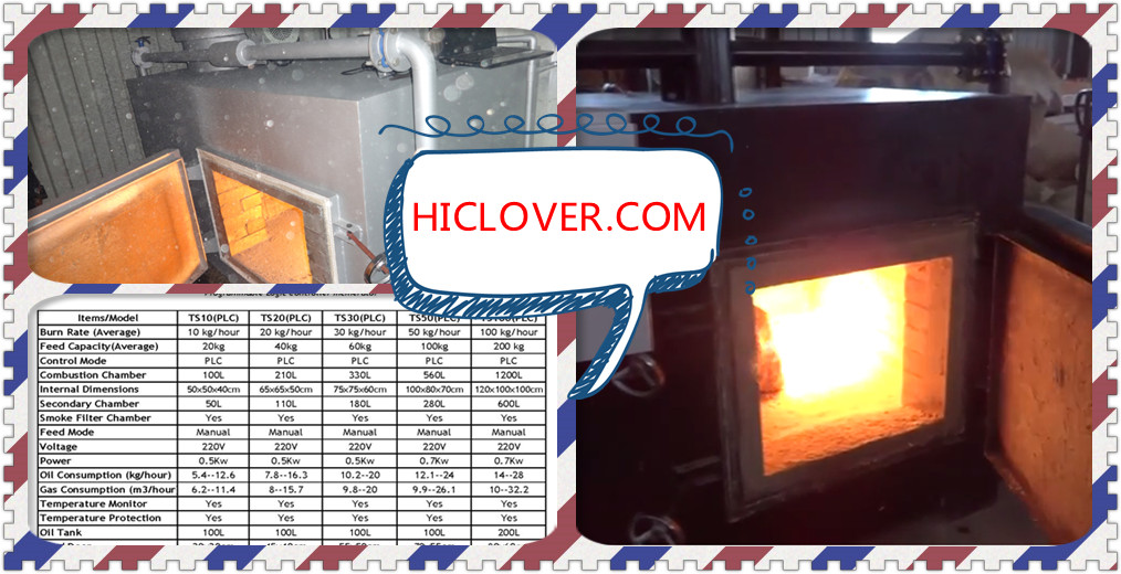
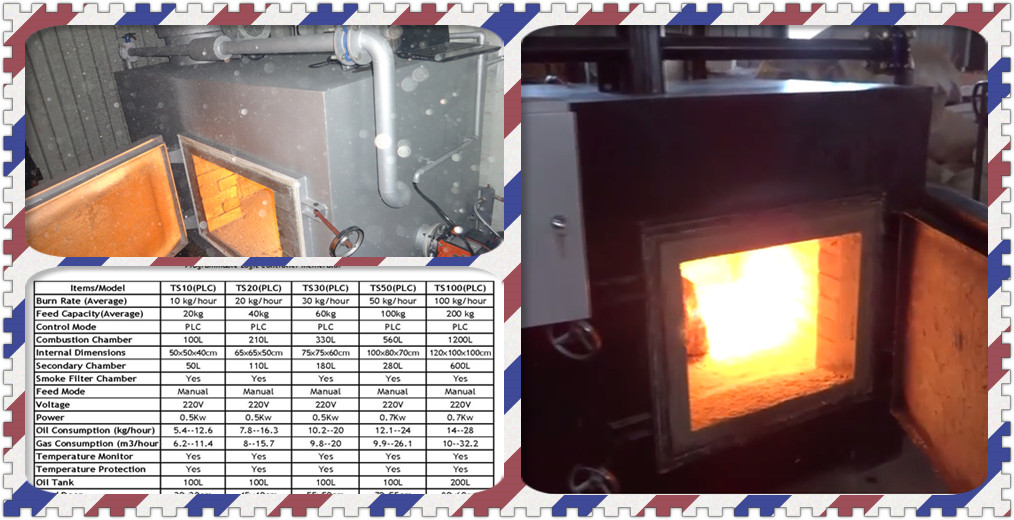
Provide incinerator having a capacity of less than [75] mph hour, dependent on operating the incinerator no more than 8 hours continuously per day, and also to be acceptable for burning medical waste parts which have a water content as high as 85 per cent by weight.
Supply furnace using an inside volume, exclusive of the space occupied by the refractory hearths and walls, of not less than two cubic meters having a primary combustion chamber amount above the burning hearth of less than 1.5 cubic meters, either Supply an entire waste burning system containing combustion air fan, primary and secondary burners, air distribution and burner controllers, ducts, breeching, stack, bottom ash conveyor and set, nourish rams, flame tube water tube, air compressors, and slurry pumps, and water pumps, and fly ash collection strategy.
2.5OPERATING AND PERFORMANCE REQUIREMENTS
2.5.8Weight Reduction
Supply an incinerator effective at reducing junk to an ash perhaps maybe never to exceed 5 per cent of the whole combustible charges when analyzed as stated.
2.5.9Stack Discharge
Supply pollution control equipment to satisfy applicable emission regulations and also utilize most rigorous requirements.
C.Enclose or guard belts, pulleys, chains, gears, couplings, projecting setscrews, keys, and other rotating parts located at which any person may arrive from close proximity thereto. Guard and cover high-temperature equipment and piping located where they could undermine personnel or make a fire hazard with insulation of type specified for service.
The centrifugal type with forward-curved blades, also statically and dynamically balanced fan wheels adhere to the fan standards of AMCA 99, along with CID A-A-59222, centrifugal furnace fans, ranked for flowrate, pressureand power, speed of spinning, and efficiency in accordance with AMCA 210. Provide induced draft fans, where demanded, designed for tackling hot flue gas at the maximum outlet temperature of the incinerator.
2.8.7 Ash Removal
Moisture Content (MAX)% Heating Worth J/kg
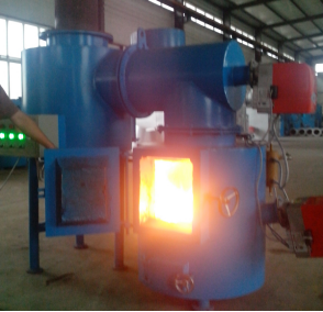
Provide an incinerator having a stable hearth in the main combustion chamber where partial conversion and burning of the combustible organic thing occurs, and also a secondary combustion chamber that absorbs the combustible gases and entrained combustible particles, with gas-tight casing structure. Provide an incinerator suitable for indoor setup including totally enclosed electric motors, and corrosion and moisture protection, and designed with mechanical charging and functionality. Incinerator will likely be an entire package-type unit, factory fabricated and assembled operating under negative air pressure and ready for attachment of all utility links.
2.6.1Kind of Waste
1- Parts per million by volume (ppmv).
A.Provide LPG burners to your primary and secondary combustion chambers, with each burner because an entire assembly including control and fuel systems, and attachments.
Provide powdered activated carbons (PAC) specifically made for its removal of mercury, dioxins, and furans having a high percentage of pore sizes in the 20 to 50 angstrom range, together using pa-c completely devolatilized.
2.3.6Pebble Quick Lime Diagnosis
Nitrogen Oxides (NOx): 2-10 ppmv, 12hour average as measured by EPA Reference Method 7 Hydrogen Chloride (HCL): 42 ppmv, or 97 percent decrease, 9-hour average as measured by EPA Reference Method 26
Provide control system together using proportioning charge of the primary air source and gas supply into the burner], and also temperature index controls or alternative signs providing a visual sign for safe loading of this incinerator and surplus elevated temperature conditions that might require control by the operator.
5- mg (mg);
2.5.10Noise
Provide site function, structural bases, and floor slabs as demanded.
•Roof Lots
Provide heap support in accordance with NFPA 82 and NFPA 211, as applicable. Provide lateral and vertical supports for outside chimneys to defy wind forces.
refractory and insulation. Play all welding according to ASME BPVC SEC IX and AWS d 1.1/d 1.1M. Supply entry doors and parts using seals to avoid emission of smoke or entrance of significant amounts of atmosphere throughout incinerator operation, and also a primary room without any openings which would permit emission of waste fluids.
2.5.8Secondary Chamber
Be aware: Your incinerators should be capable of decreasing medical waste. The composition of Type 4 squander as indicated from the following table:
WASTE VS. CONTENT
Type Non-combustible Solids (Max% Posts
A.Include in control equipment and instruments, burners and fan controllers, time clocks, brakes, operating switches, indicating lights, gauges, motor starters, fuses, alarms, and circuit elements of this control system, and also other controllers and instruments required for unit functionality, using system in accordance with the FM APP GUIDE.
b.Mount the controls and instruments on a couple of freestanding control panels handily located to the incinerator, and placed to allow functioning employees effortlessly track incinerator operations.
Install equipment and material as indicated and according to manufacturer’s written guidelines and NFPA 82, with combustion air supply and venting in accordance with NFPA 31 or NFPA 54 as applicable.
Total Hydrocarbons: 70 ppmv, 1-hour average as measured by EPA Reference Method 25 Mercury: 2-10 gr/106dscf (0.47 mg/dscm) or 85 percent decrease, 12hour average as measured by EPA Reference Method 29;
Furnish all specific tools for assembly, adjustment, setting, or maintenance of equipment specified as accessories.
•DELIVERY, STORAGE, AND HANDLING
Failure protection. Sight the flame shield sensor to find only the burner flame to which it was fashioned, using burners which are readily transferred out of fire location for review, cleaning, modification, and maintenance. Locate thermocouples from the primary and secondary chamber, convenient for a maximum temperature of 1260 degrees C 2300 degrees F. supply a continuous secondary burner which modulates from high to low flame, dependent on the temperature of the secondary room. Provide an on/off fire burner in the main chamber.
Asbestos and asbestos-containing products are prohibited.
2.10.2Detail Installation Drawings
10
Protect all equipment delivered and placed in storage from the elements, humidity and temperature variations, dirt and dust, or other contaminants.
•EXTRA MATERIALS
Play all welding according to ASME BPVC SEC IX and AWS D 1.1/D-1.1M by welders certified to have passed qualification tests utilizing procedures covered in AWS B 2.1/B2.1M.
2.10.4Special Tools
C.Provide controls actuated by means of a thermocouple or shielded bi metallic detector, with all the mounting, flame structure, and faculties of each burner acceptable to your incinerator room where the burner has been installed. Flame impingement on the incinerator wall socket isn’t permitted.
Typical values are as follows or less:
Furnish equipment fulfilling the noise criteria specified herein through equipment structure, acoustic insulation, usage of coil silencers, or alternative methods provided under this arrangement.
1.3.6 Controls and Instrumentation
Adjust all of the emission limits to 7 percent oxygen, dry basis. These definitions were utilized previously:
Biological and Pathological Waste Incinerator is characterized as animal and human remains, such as organs, animal carcasses, and powerful organic wastes from hospitals, laboratories, slaughterhouses, animal pounds, and similar sources. This type of waste contains up to 85 per cent moisture and more than 5 per cent incombustible solids, and it has a heating value as low as 23-30 kJ/kg 1,000 BTU per pound as fired.
Provide connectors to connect the incinerator to the heap unless the heap is attached directly to the incinerator, prior to NFPA 211.
Give you the help of the manufacturer’s representative experienced in the installation, modification, and performance of the apparatus specified, who will supervise the installing, adjusting, and commissioning and compliance testing of the equipment.
Sulphur Dioxide (SO2): 4 5 ppmv, 12hour average as quantified with a CEMS;
Provide a controller actuated refractory lined damper which modulates secondary, under fire, and over flame atmosphere, made with steel conforming to ASTM A1011/A1011M, not less than 1.52 mm 16-gauge thick, operating without noise or flutter, and electric motor.
Find the connector in the absolute minimum clear vertical distance of 2450 mm 8 feet above a floor.
•Draft Equipment
Include sensory and wind loading Within the design exposure SEISMIC PROTECTION FOR MECHANICAL EQUIPMENT
Necessary to your motor control specified, as well as sufficient size to drive the equipment at the
3- arid standard cubic meters (dscm); 4- g (gr);
Specified capacity without exceeding the nameplate rating of the motor. Provide manual or automated control, protective or signal devices required for the operation specified, and any control wiring required for controls and devices specified however, not shown.
2.10INCINERATOR
Construct adsorber with 4.76 mm 3/16 inch stainless steel plate, ASTM A36/A36M or ASTM A283/A283M, markers C, B, or D. Space outside stiffeners as necessary to provide support to your skin. Seal weld all welded seams. Design joints to be constructed water and air tight. Design adsorber for a gas pressure of plus or minus 635 mm 25 inch water flow, or as demanded by the machine operation, whichever is greater, with any panel deflection not exceeding L/240.
•Gas Flow
Shop Drawings: Detail Installation Drawings
Cadmium: 22 gr/106dscf (0.05 mg/dscm), 12hour average as measured by EPA Reference Method 29;
Design roof purloins and beams for dead load along with an extra 0.24 kPa 5 psf uniformly spread load plus an extra 22.4 kN 5000 pound concentrated load also drift factor where applicable]. Determine wind uplift forces according to ASCE/SEI 7-05 Department 6 with a 100-year recurrence interval as well as requirements.
•Floor Loads
NEMA 4 control panels for exterior installations with electric strip heaters for corrosion control. Flush mount all controllers, instruments, and other equipment at the factory and also examine the assembly before shipment. Furnish a lock and two keys. All controllers and instruments shall be identified with nameplates.
Provide heat-resistant plastic Super Duty fireclay refractory conforming to ASTM C 27. The minimum depth of vinyl or throw able refractory is 1-10 mm 4 for walls and 1-10 for hearths. Attach refractory walls to the casing using metal steel or refractory anchors to form a monolithic structure that may withstand heat and support that the walls having a safety factor of 4. Prevent bulging and degradation of refractory due to heat stress by reinforcing, expansion ligaments, tendons, and also anchors.
2.5.11Exterior Walls
Factory paint supplies and component pieces with the manufacturer’s standard finish. Provide a weather resistant finish on most of items located away from the construction.
PART 3 EXECUTIONS
1.3EXAMINATION
5
Sterile the inner surfaces of the outer casing of the incinerator, the outside surfaces of the outer casing, the control panel, and piping, except corrosion-resistant steel, to base metal for removal of rust and oil until primer is applied at the factory.
1.4.2Factory Painting
Noise level at 305 mm 1 foot in any incinerator component will not exceed 85 dBA. Provide sound-dampening devices in your equipment.
2.5FURNACE CONSTRUCTION
2.5.7Primary Chamber
B.Make proper provision for contraction and expansion between incinerator base and floor; package the joint using suitable non-asbestos rope and match with appropriate chemical that will not become soft in a temperature of 40 degrees C 100 degrees F.
Provide dampers to place the atmosphere for the proper burning of the waste substances. Size ducts to minimize pressure drops, constructed of sheet steel conforming to ASTM A1011/A1011M, with seams and relations atmosphere tight.
D.Provide things such as a cat walk, strand, ladder, and guardrail where demanded.
Provide insulation conforming to ASTM C 612, Class 5 and made to be used with masonry or reinforced concrete or noncombustible material, with a flame resistant rating of less than 3 weeks, to prevent damage to the base from excess heating. As a minimum, provide insulation depth to limit the temperature of the outer casing to 66 degrees C 150 degrees F maximum within an ambient temperature of 21 degrees C 70 degrees F once the machine is operating at full-rated capacity.
Indicate and clearly identify an instrument evaluation group close every thermocouple well to join mobile equipment to verify installed equipment.
B.Provide each major part of equipment with the manufacturer’s name, address, type or style, model or serial number, and catalog number on a plate secured to the apparatus
Give you the gas flow to every module together using internal deflector plates developed to provide uniform gas distribution and velocities throughout the machine.
2.3.4Product Handling and Preparation System Supply an entire system to receive, store, and also supply product to the spray-dry adsorbers, with the capability of supplying sufficient product to your incinerator operating at 120 per cent of full load. Include in the system, but usually do not limit to, product storage silo complete with vibrating bin discharger, flexible relations, gravimetric feeders, attrition slaker, [lime] slurry and water Pumps, slaked product storage tank, and agitators.
D.Provide each burner using FM APP GUIDE recorded and approved flame
NOTE: Indicate design wind force that the stack will have to withstand. Additionally include in atomic layout seismic immunity, and organize with subparagraph Lateral Loads under paragraph
Performance: Fixing and Testing.
Inter Lock automatic control circuit systems and manual switches to stop hazardous conditions or the release of excessive levels of air pollutants.
•Control Panel
Construct bypass dampers to offer a reduction rate of less than one percentage in 1.5 times the maximum operating pressure.
2.4.4Test Holes and Test Groups
1Provide a sectional, circular crosssection exhaust stack of the kind, size, and quantity of segments in accordance with certain requirements of the stack and refractory manufacturer to adequately support the refractory lining, empower expansion, and also prevent cracking of this refractory; conforming to NFPA 211. Secure the refractory to the casing by steel anchors.
Provide electrical motor-driven equipment as stated, complete with motors conforming to NEMA MG 1, motor starters, and controllers, with enclosures as indicated. Provide electrical equipment, including motors and wiring with electrical traits as specified or suggested. Provide motor starters finish with thermal overload protection and other appurtenances
Lead: 44 gr/106dscf (0.10 mg/dscm), 12hour average as measured by EPA Reference Method 29
Provide a buff capable of delivering sufficient air for burners and less than 150 percent compared to mandatory by manufacturer.
Provide working floors, stairs and access systems for operation and maintenance, designed for
Construct observation vents of black steel or cast-iron tube or casing having a minimum depth of 3.42 mm 10 gauges and provided with heat-resistant glass cover, or an angular steel frame and closed plate with handle, for operation without gloves or other protective devices. Extend the tube or duct from the outside of the casing to less than half the depth of the refractory lining, and then weld the frame to the casing, to offer a gas-tight refractory opening.
Provide flue gas cleaning equipment capable of meeting emission requirements specified utilizing lime
2.8.2 Burners
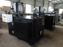
Provide 4 mm sheet steel walls reinforced with steel framing and also provided with door frames and also installed on structural steel skids.
2.5.12Hearth
Owner and/or his representative endorsement are necessary for submittals. SUBMITTAL PROCEDURES:
By Weight)
5
B.Secure refractory to the doors in order to prevent sagging. Taper refractory edges to clear door-frames throughout movement of doors. Weld metal steel hooked bars to door cover to anchor the refractory, to enable safe operation by one person, and maintaining equilibrium of door manages to empower performance of doors without gloves or other protective devices.
c.Interlock charging doors primary burners and atmosphere source therefore that burner ignition shuts off and Underfire atmosphere dampers close when doors open. Gasket do or finishing must be together without non- asbestos packing.
Submit free parts data for each different item of material and equipment specified, after approval of detail drawings, and Contain a comprehensive list of parts and supplies, with current unit prices and source of source, and a list of these spare parts recommended by the manufacturer.
Submit detail setup drawings for your incinerator, base, stackand waste feed system, fuel burning equipment, ash removal system, flue gas cleaning system, and controllers. Include at length drawings all of equipment settings and relations, complete electrical wiring, controls, and connection diagrams and signify clearances required for maintenance and functionality.
2.10.3Welding
Provide test holesnear the evaluation group exhibited on the contract drawings, and match conventional pounds, 50 mm 2 inch diameter, black steel pipe welded to the casing. Extend the sleeve from the exterior of the casing not less than half the depth of the refractory lining. Form the
refractory opening by the conclusion of the pipe to the interior surface to shield the end of the sleeve from reflected heat, and match a threaded screw cap. Submit a copy of the Instrument Readings to the Contracting Officer.
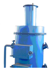
2.3FLUE GAS CLEANING SYSTEM
Supply a whole flue gas cleaning system (FGC) composed of a Powdered activated carbon dioxide system, and a acid gas scrubber system capable of continuous functioning performance suitable for the incineration capacity and schedule defined.
Provide an incinerator effective at burning typical medical waste including plastics, paper of various kinds, and also a small portion of Type 4 (Pathological) waste.
Introduce combustion Underfire atmosphere to the key chamber below the waste material through ducts located across the side of the hearth]. Control over flame atmosphere with automatically controlled atmosphere intake vents in the backwall, for completing combustion of combustible substances to gases, or for reducing temperatures.
Provide a primary burner using an input power capable for keeping the absolute minimum continuous temperature at the secondary room of 871 degrees C (1600 degrees F), and also a minimum continuous temperature of 760 degrees C (1400 degrees F) in the roof close to the exit of the primary chamber.
b.Provide electrically spark-ignited burners governed by a varying set point indicator-controller flexible from minus zero to 1371 degrees C (minus 17 to 2500 degrees F) to use over the temperature limits recommended by the manufacturer.
Provide access openings in strategic locations for cleaning, inspection, and maintenance, being a gas tight quick-opening type. Elevate the adsorbers to permit 2130 mm feet access under the lowest point which would amass particulates. Find an access door in this lowest indicate permit removal of accumulated particulate; built to start using an accumulation of material .
•Structure
NOTE: Indicate the type and class of motor enclosure predicated upon the environment where the motor is to be properly used.
Provide volume storage capacity for several required products to sustain the absolute minimum operating amount of one week between deliveries.
2.3.3Adsorbers
•Access
C.Provide incinerator supports which permit free expansion and contraction of each part of the incinerator without placing undue stress on any region of the incinerator or feeling. Place anchor bolts accurately, and of decent length to install the incinerator. When embedded in concrete, then provide anchor bolts plates welded on the head and protect against damage before apparatus is installed.
1.5.7Stack Support
Carbon Monoxide (CO): 50 ppmv, 12hour ordinary as quantified by means of a Continuous Emissions Monitoring System (CEMS)
Provide and discover signaled, shooting and operating gear, including as shovel or mist shovel, hoe, rake, piece bar with metal handles, regularly employed for cleaning and firing incinerators, and also a fire tool rack. Provide steel stand, for example hinges along with other appropriate methods for preserving the gear in a fantastic way.
Provide an abrasion resistant refractory hearth made of heat-resistant, thermal-insulating clay conforming to ASTM C 401, Class R vinyl or throw able type, high-duty class, capable of supporting not less than double as hourly burning speed and preventing leakage of fluids.
2.5.13Doors
Certificates: Incinerator Operation and Maintenance Data Operating and Maintenance Instructions: Data Package.
2.10QUALITY ASSURANCE
2.10.1Asbestos Prohibition
•Access
Provide access openings at strategic locations for inspection, cleaning, and maintenance, all being a gas tight quick-opening type. Elevate the adsorbers to permit 2130 mm 7 feet access under the lowest point which would collect particulates. Locate an access door at this lowest point to permit removal of accumulated particulate; designed to open with an accumulation of material above it.
•Construction
Construct adsorber with at least 4.76 mm 3/16 inch thick steel plate, ASTM A36/A36M or ASTM A283/A283M, grades B, C, or D. Space external stiffeners as required to provide support for the vessel skin. Seal weld all structurally welded seams. Design joints to be assembled air and water tight. Design adsorber for a gas pressure of plus or minus 635 mm 25 inch water gage, or as required by the system operation, whichever is greater, and with any panel deflection not exceeding L/240.
•Gas Flow
Provide the gas inlet to each module with internal deflector plates designed to provide uniform gas distribution and velocities through the unit.
2.3.4Product Handling and Preparation System Provide a complete system to receive, store, and supply product to the spray-dry adsorbers, with the capability of supplying sufficient product for the incinerator operating at 120 percent of full load. Include in the system, but do not limit to, product storage silo complete with vibrating bin discharger, flexible connections, gravimetric feeders, attrition slaker, [lime] slurry and water Pumps, slaked product storage tank, and agitators.
2.3.5Powdered Activated Carbon
Provide powdered activated carbons (PAC) specifically made for the removal of mercury, dioxins, and furans with a high percentage of pore sizes in the 20 to 50 angstrom range, with PAC completely devolatilized.
2.3.6Pebble Quick Lime Analysis
Provide flue gas cleaning equipment capable of meeting emission requirements specified using lime
2.8.2 Burners
a.Provide LPG burners for the primary and secondary combustion chambers, with each burner as a complete assembly including fuel and control systems, and accessories.
Provide a primary burner with an input capacity capable for maintaining a minimum continuous temperature in the secondary chamber of 871 degrees C (1600 degrees F), and a minimum continuous temperature of 760 degrees C (1400 degrees F) at the roof near the exit of the primary chamber.
b.Provide electrically spark-ignited burners regulated by a variable set point indicator-controller adjustable from minus zero to 1371 degrees C (minus 17 to 2500 degrees F) to operate within the temperature limits recommended by the manufacturer.
c.Provide controllers actuated by a thermocouple or shielded bimetallic sensor, with the mounting, flame shape, and characteristics of each burner suitable for the incinerator chamber in which the burner is installed. Flame impingement on the incinerator wall is not permitted.
d.Provide each burner with FM APP GUIDE listed and approved flame
failure protection. Sight the flame safeguard sensor to detect only the burner flame for which it is designed, with burners which are easily moved out of firing position for inspection, cleaning, adjustment, and maintenance. Locate thermocouples in the primary and secondary chamber, suitable for a maximum temperature of 1260 degrees C 2300 degrees F. Provide a continuous secondary burner which modulates from high to low fire, based on the temperature of the secondary chamber. Provide an on/off firing burner in the primary chamber.
•Stack
Important: minimum height of the chimney should less than 15 meter measured from roof of top roof of incinerator room and not less than 5 meter higher than any building in distance of 1km from incinerator room, also the outlet velocity of flue gases should not less than 7 Meter per second
1Provide a sectional, circular cross section exhaust stack of the type, size, and number of sections in accordance with the requirements of the stack and refractory manufacturer to adequately support the refractory lining, permit expansion, and prevent cracking of the refractory; conforming to NFPA 211. Secure the refractory to the casing by steel anchors.
2Attach a corrosion-resistant steel spark arrestor fabricated of 1.21 mm 18-gauge, 13 mm 1/2 inch mesh wire screen to the top of the stack. Provide a corrosion-resistant steel weather cap. The
temperature of the casing shall not exceed 50 degrees C in an ambient temperature of 21 degrees C 70 degrees F. Provide adequate support for any stack installed on top of the incinerator without placing any of the load on the refractory walls of the incinerator.
•Breeching
Provide connectors to connect the incinerator to the stack unless the stack is attached directly to the incinerator, in accordance with NFPA 211.
Locate the connector at a minimum clear vertical distance of 2450 mm 8 feet above the floor.
•Draft Equipment
Provide equipment which supplies the correct amount of air to permit complete controlled combustion. Include forced draft fans, draft gauges, dampers, damper actuators, linkage, and appurtenances necessary to maintain a negative draft in primary chamber in order to provide optimum performance at all operating rates.
•Air Ducts
Introduce combustion under fire air to the primary chamber below the waste material through ducts located along the side of the hearth]. Control over fire air with automatically controlled air intake ports in the back wall, for completing combustion of combustible materials into gases, or for reducing operating temperatures.
Provide dampers to set the air for the proper burning of the waste materials. Size ducts to minimize pressure drops, constructed of sheet steel conforming to ASTM A1011/A1011M, with all seams and connections air tight.
•Fan
Provide a fan capable of delivering sufficient air for burners and not less than 150% than the required by manufacturer.
The centrifugal type with forward-curved blades, and statically and dynamically balanced fan wheels Comply with the fan standards of AMCA 99, and CID A-A-59222, centrifugal furnace fans, rated for flow rate, pressure, power, speed of rotation, and efficiency in accordance with AMCA 210. Provide induced draft fans, where required, designed for handling hot flue gas at the maximum outlet temperature of the incinerator.
2.8.7 Ash Removal
Provide the unit with provisions for automatic removal of the ash through the cleanout door upon completion of the burnout and cool-down cycles. Ash removal shall be as indicated for use with portable containers.
1.4PAINTING AND FINISHING
1.4.1Treatment
Clean the inner surfaces of the outer casing of the incinerator, the exterior surfaces of the outer casing, the control panel, and piping, except corrosion-resistant steel, to base metal for removal of oil and rust before primer is applied at the factory.
1.4.2Factory Painting
Factory paint equipment and component items with the manufacturer’s standard finish. Provide a weather resistant finish on all items located outside the building.
PART 3 EXECUTIONS
1.3EXAMINATION
After becoming familiar with all details of the work, verify dimensions in the field, and advise the Contracting Officer of any discrepancy before performing the work.
1.4MANUFACTURER’S SERVICES
Provide the services of the manufacturer’s representative experienced in the installation, adjustment, and operation of the equipment specified, who will supervise the installing, adjusting, and commissioning and compliance testing of the equipment.
1.5INSTALLATION
Install equipment and material as indicated and in accordance with manufacturer’s written instructions and NFPA 82, with combustion air supply and ventilation in accordance with NFPA 31 or NFPA 54 as applicable.
1.5.6Foundation
a.Construct the incinerator foundation using CAST-IN-PLACE CONCRETE. Extend the foundation a minimum of 1 m 3 feet beyond the incinerator on 3 sides and not less than 2.5 m 8 feet on the side where the ashes are removed. Install the incinerator in accordance with manufacturer’s written instructions.
b.Make proper provision for expansion and contraction between incinerator foundation and floor; pack the joint with suitable non-asbestos rope and fill with suitable compound that will not become soft at a temperature of 40 degrees C 100 degrees F.
c.Provide incinerator supports which permit free expansion and contraction of each portion of the incinerator without placing undue stress on any part of the incinerator or setting. Set anchor bolts accurately, and of adequate length to install the incinerator. When embedded in concrete, provide anchor bolts with plates welded on the head and protect against damage until the equipment is installed.
1.5.7Stack Support
NOTE: Indicate design wind force that the stack will have to withstand. Also include in structural design seismic resistance, and coordinate with subparagraph Lateral Loads under paragraph
Provide stack support in accordance with NFPA 82 and NFPA 211, as applicable. Provide vertical and lateral supports for exterior chimneys to withstand wind forces.